 Chip Loder
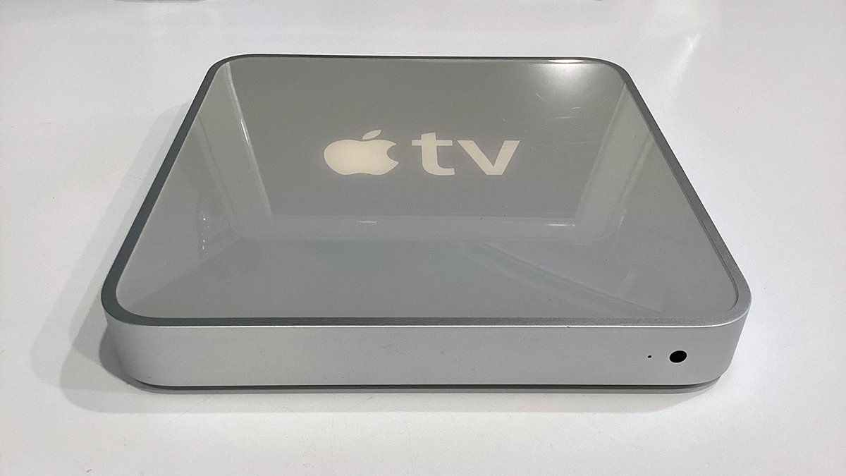
Apple first released the Apple TV set-top box in 2006. Here's how to refurbish and restore one of the original units, to make the set-top box as good as new.
All through the 1990s, Apple had been toying with the idea of making a set-top TV box for home users. Like a cable TV box, Apple wanted to have a TV platform that was compact, inexpensive, and easy to use.
Apple's first stab at a TV device was in the early 1990s when it started a project called Apple Interactive Television Box. It was loosely based on a Mac of the time called the Quadra 605.
But by 1995, Apple had abandoned the project, and work began to devise a new machine that was smaller and simpler. Nine years later, the result was the first Apple TV.
Unlike today's Apple TV, the original device didn't have an App Store. Instead, Apple's iTunes app was used to synchronize movies, music, photos, and other media to the device over a network, or via the USB port.
Many of these devices are still available online, in working condition at low prices.
We found ours on eBay for less than $15. However, its internal drive had been wiped of the operating system, which may present a challenge for some users.
The technical specifications for the first-generation Apple TV can be found at everymac.com.
Based on Mac OS X Tiger
The first generation Apple TV released to the public was actually a minimized Mac, running a specially modified version of Mac OS X Tiger (10.4). The machine was based around an Intel Pentium M chip running at 1GHz, an Nvidia GeForce Go 7300 GPU, and 256MB RAM.
Design-wise the device could theoretically support 1GB of RAM, although none of the devices ever shipped with more than 256MB. As we will see below, it is possible to hack the Apple TV to support 512MB, but it's very difficult.
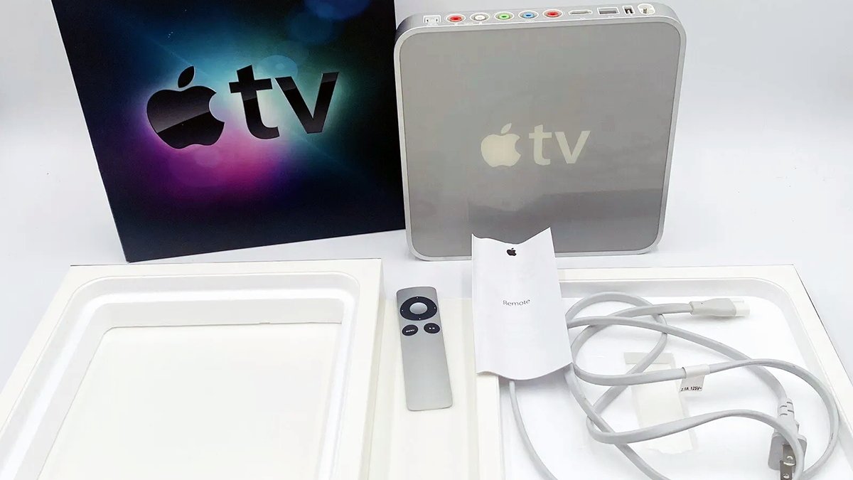 Original 1st generation Apple TV with box.
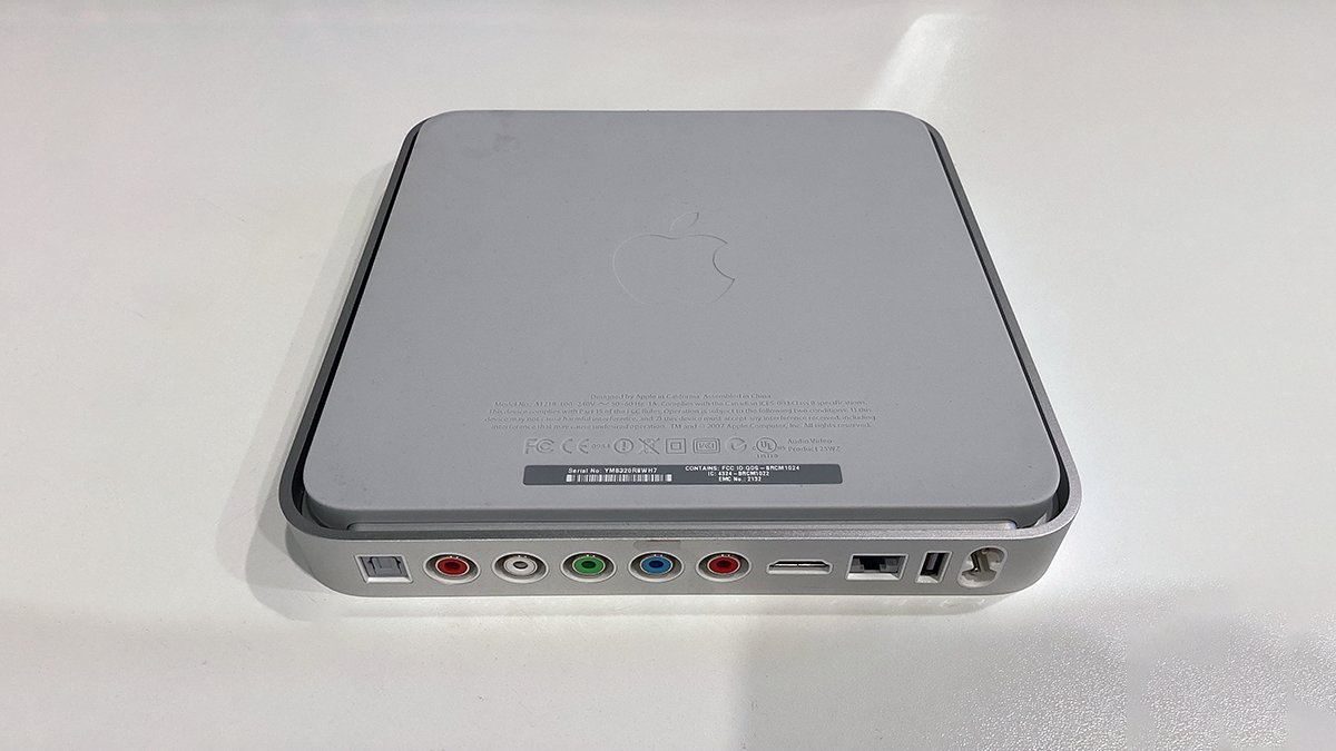
On the rear of the device are a variety of ports: power, USB, Ethernet, HDMI, component video, analog stereo audio, and optical audio (TOSLINK). All first generation Apple TVs also included WiFi built-in.
The device is built around a metal frame, a clear and white lucite top, a metal bottom cover, and a single large rubber pad on the bottom held on with adhesive. The motherboard and most of the electronics are actually built into the top of the device.
There's only a single internal 2.5-inch ATA hard drive secured to the bottom metal cover with four Torx screws.
In this article, we'll look at how to disassemble, clean, restore, and optionally upgrade the original Apple TV.
 Bottom view: the large rubber foot, metal cover, and metal frame.
Disassembly
Before proceeding, we should warn you that disassembling the original Apple TV requires some skill and some special tools.
You should also ask yourself the question: Am I willing to accept some small minor damage to my Apple TV in exchange for cleaning, upgrading, and repairing it?
This question is important, because due to the age of the device, it may be impossible to open it without incurring some small damage to parts (most notably the bottom foot and internal fan).
Having said that, it's also completely possible to perform the repair without causing any permanent major damage - if you are careful. Also, be aware there are some high voltages in the Apple TV power supply (250V) and it's possible to get shocked in some cases if you are not careful.
Attempt this repair at your own risk.
Tools
As with previous refurbs, you'll need a special set of tools to open the machine:
- A 4.5-inch (11.5cm) wall spackling tool
- A medium magnetized Phillips-head screwdriver
- A tiny magnetized Phillips-head electronics screwdriver, or jeweler's screwdriver
- A small flat plastic or metal spudger
- Small Torx screwdrivers
- Scissors
- A small hobby knife
- A tiny artist's paintbrush
- A multimeter
- Compressed air or an air compressor
- A bright flashlight
- Bright room lighting
- Optionally a microscope, or a small magnifier or jeweler's loupe
- Kapton tape and masking tape
- A CR2032 replacement button-cell battery
Step 1: Remove the rubber foot
Perhaps the most difficult step in opening your Apple TV is removing the large rubber foot. This part is actually two layers of rubber fused together and glued to the bottom metal cover with plastic adhesive.
When trying to remove the foot, it will likely begin to separate and tear in spots where the rubber had bonded to the adhesive. For this reason, you must use a wide spacking knife to pry the foot off very slowly.
To begin, place the device face-down on a well-lit surface on top of a soldering mat or soft hand towel with the rear ports facing towards you. Using both hands gently and slowly begin prying up the rubber foot at one corner with your fingers.
Go slowly and periodically stop to check if the bottom of the rubber foot is tearing on the outside. If it is, stop and use the spackling knife to get under the adhesive and pry it up along with the foot.
Work from one corner horizontally across to the other, then forward evenly towards the front of the device. Stop at intervals to check for tears on the outside.
If tears do occur it's not the end of the world - if you stop immediately and use the knife to peel the glue off, the tearing can be minimized and won't be obviously visible on the outside.
You may also want to try heating the foot slightly with a hot air gun or hair dryer to soften the glue, but if the adhesive is too old and brittle, this may not have much of an effect.
Finally, remove the rubber foot entirely as you move forward towards the front of the device. Once all the glue is separated, the foot will come free. Set it aside for now.
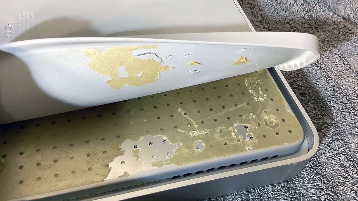 Rubber foot removal and small tear damage. Proceed slowly.
Step 2: Open your Apple TV
If there is any residual glue covering the four Torx screws on the bottom cover, remove it with a hobby knife, then remove the four screws.
These screws hold the bottom cover to the top lid. There are four more Torx screws that hold the internal ATA/IDE hard drive to the bottom cover - but don't remove those yet.
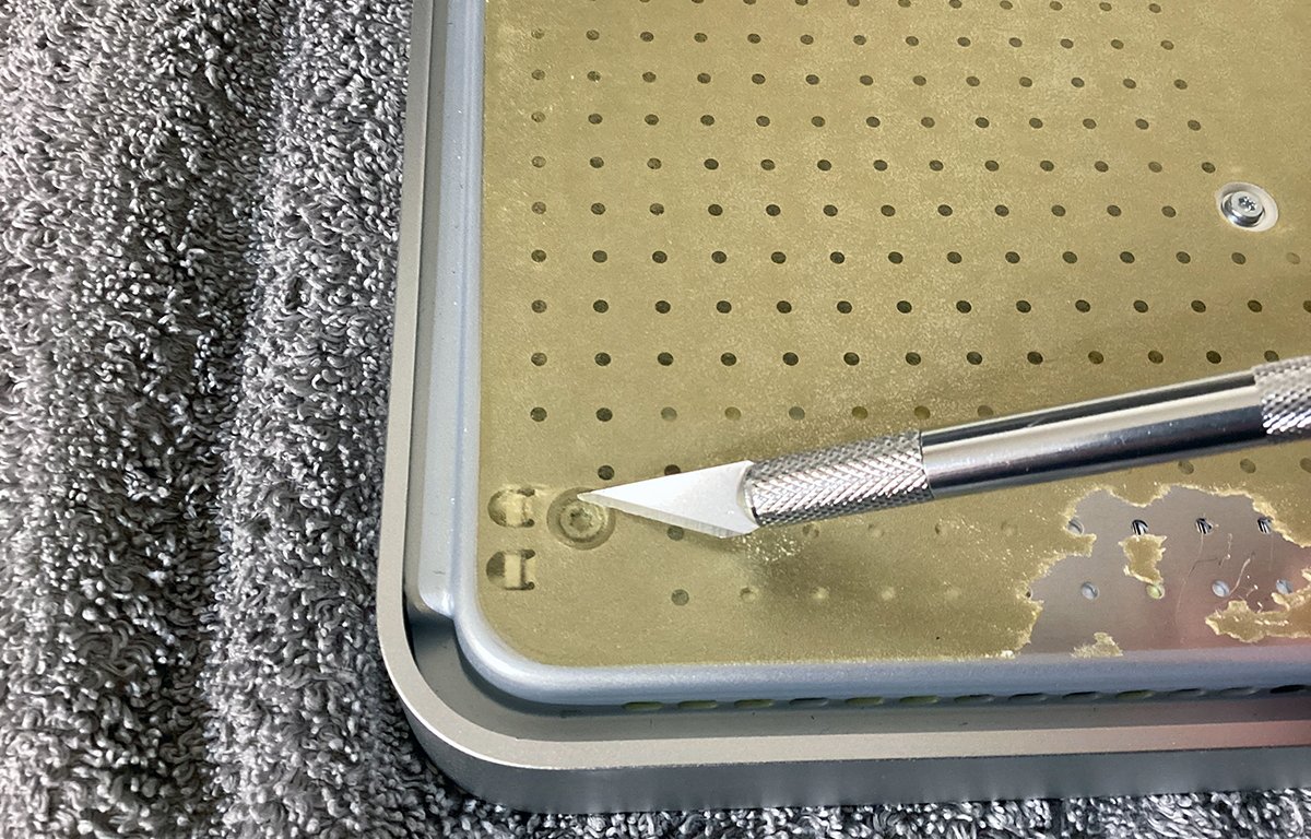 Remove excess glue from the corner Torx screws using a hobby knife.
Step 3: Remove the hard drive
Next, flip the bottom cover over, and remove the hard drive's ATA ribbon cable from the connector on the motherboard. Once it's free, flip it back over and remove the four Torx screws holding the drive to the cover.
Detach the ATA cable and inspect it for damage. Clean both the drive and cable with compressed air followed by a damp cloth. Also, clean the inside of the cover to remove any dust.
Set all three parts aside for later.
Note that unlike today's computers, the 1st generation Apple TV used ATA/IDE drives. 2.5-inch ATA drives were the standard for most laptops in the late 1990's. SATA hadn't yet been widely deployed at the time.
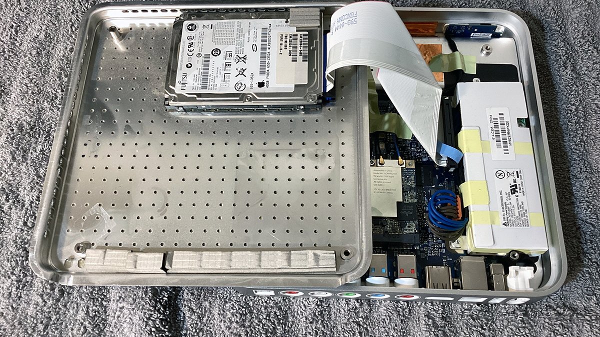 Remove the ATA drive, its ribbon cable, and the cover.
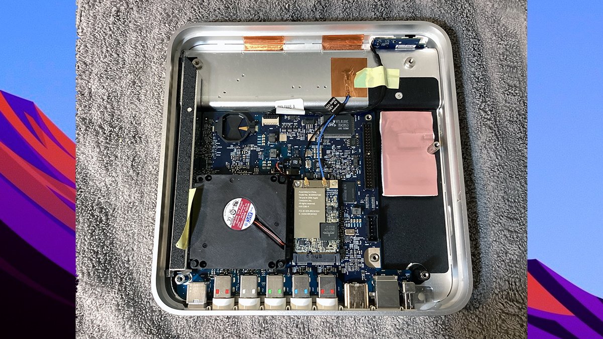
Once the drive and cover are free, we can inspect the motherboard and main components. Clockwise from upper left, they are:
- CR2032 coin-cell battery
- Network and LED/remote wires
- ATA connector
- Power supply
- Rear ports
- WiFi card
- Fan
- Lid support/heat conduit
Above the motherboard is a small internal space where the wireless antennae reside. Unless your Apple TV is very dirty inside, there's no need to open this cover.
Note that the small heat conduit next to the fan is made of aluminum. This part acts as both a heat spreader which conducts fan exhaust heat to the metal frame, and acts as a support for the bottom cover.
The heat conduit is held down by a metal post at the bottom and a single Torx screw at the top. You won't be able to access this screw without the correct size Torx mini screwdriver that can fit through the small hole above it.
Actually, there's a way around this if you don't have the correct tool, which we'll get to below.
There are actually three parts to the top cover: a metal plate the motherboard is mounted on, a metal frame, and the clear/white plastic top. All three parts are held in place until you remove the heat conduit and its two screws (and the WiFi card).
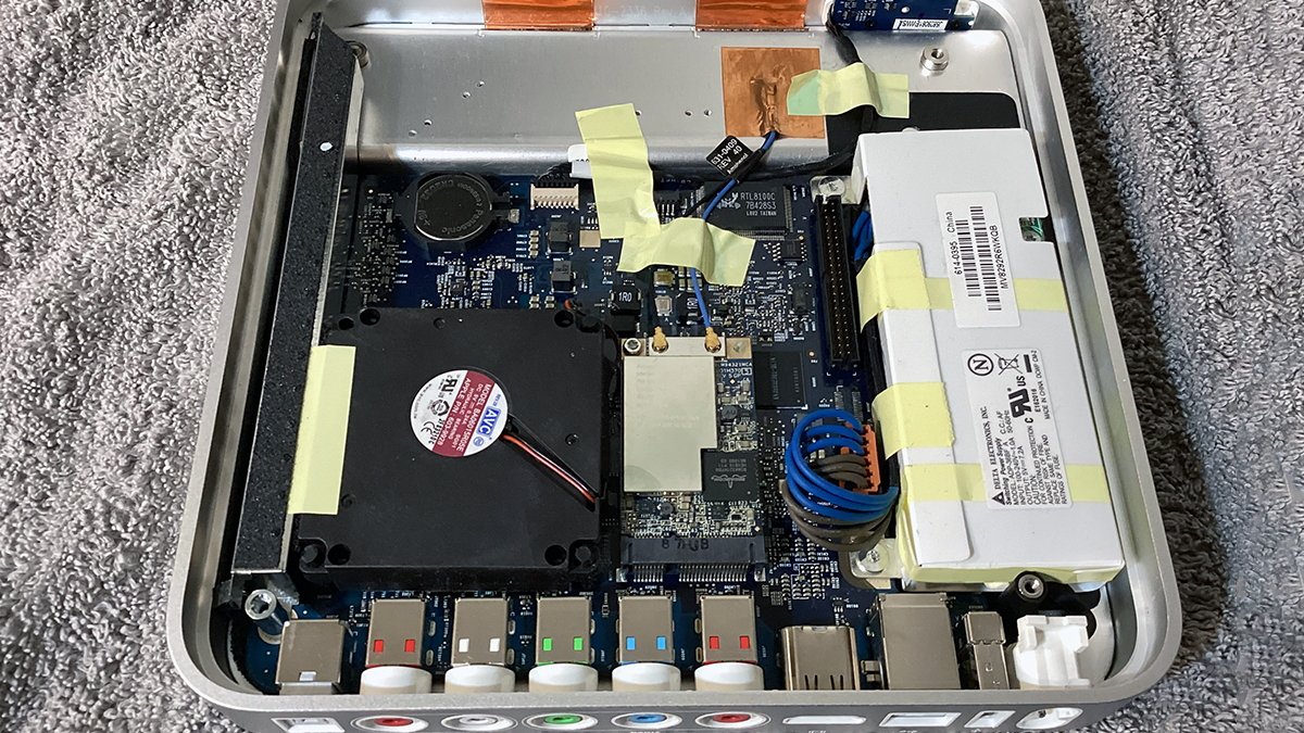 Apple TV's motherboard and case.
Step 4: Remove and test the battery
Using a hobby knife, remove the CR2032 coin-cell battery as shown. Be careful not to short anything, and not to damage the plastic battery holder either.
The best way to remove the battery is to insert a hobby knife into the holder at the bottom right or top edge and pry in the opposite direction. The battery will pop out of the holder.
Remove the battery quickly so it doesn't touch any motherboard components and short them.
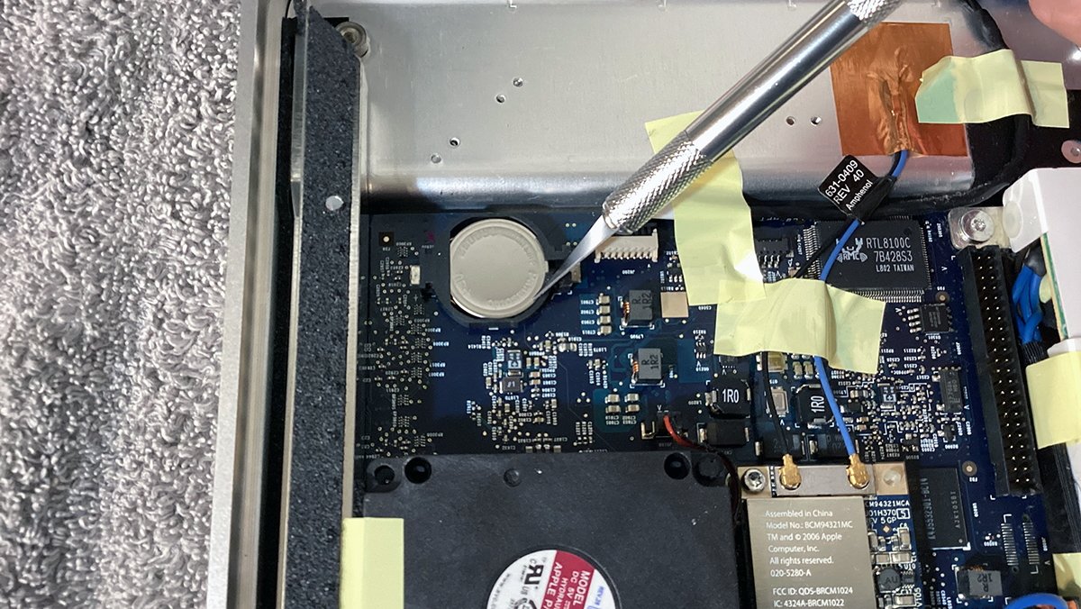 Remove the CR2032 battery using a hobby knife.
Test the battery using a multimeter by setting it to 20V DC (the side with the dotted lines on it). The correct full voltage for CR2032 is 3.3V. Ours measured 2.89 volts - a bit below normal.
We decided to replace the battery anyway with a new one. However, do this last after the machine is reassembled.
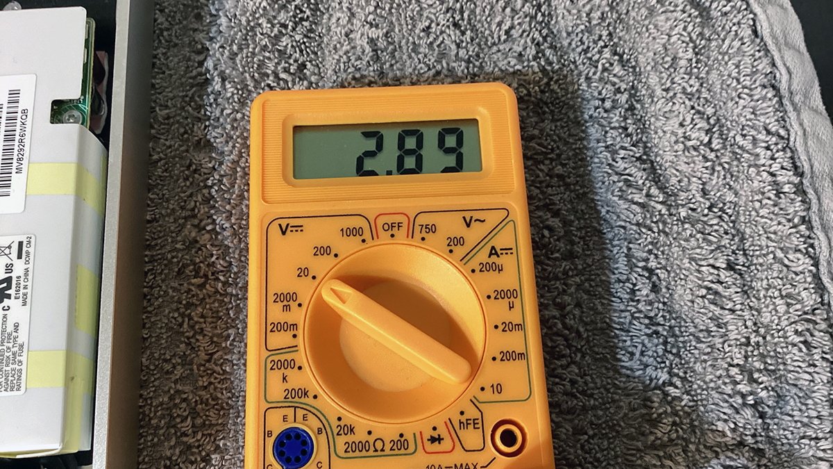 Test the battery with a multimeter. Correct max voltage is 3.3V.
Step 4: Test power
At this point, you can plug your Apple TV into a wall outlet to see what the front light shows. The front panel LED should flash a steady amber.
If it doesn't then it means there's some other hardware failure other than the missing hard drive and OS.
If you do get some other error, the machine will need repair, or if you are an electronics expert, further diagnosis.
Make sure not to touch any part of the power supply at this point. Inside the power supply are high-voltage 250V capacitors and if you touch them with your bare hands it's likely to knock you off your feet or worse.
Standard US household outlet current is 120V, and the Apple TV power supply is designed to handle this and 240V for other countries such as in Europe and the UK. This is enough voltage to electrocute humans.
It's for this reason the power supply is wrapped in an insulating plastic cover and sealed with tape. Even so, it's still dangerous when live.
Be aware even after being disconnected capacitors inside power supplies can retain their voltages for several minutes.
Proceed with caution.
If your Apple TV's power supply isn't working, you'll need to remove it in order to replace it. This task is for advanced users so we'll leave this as an extra step at the end.
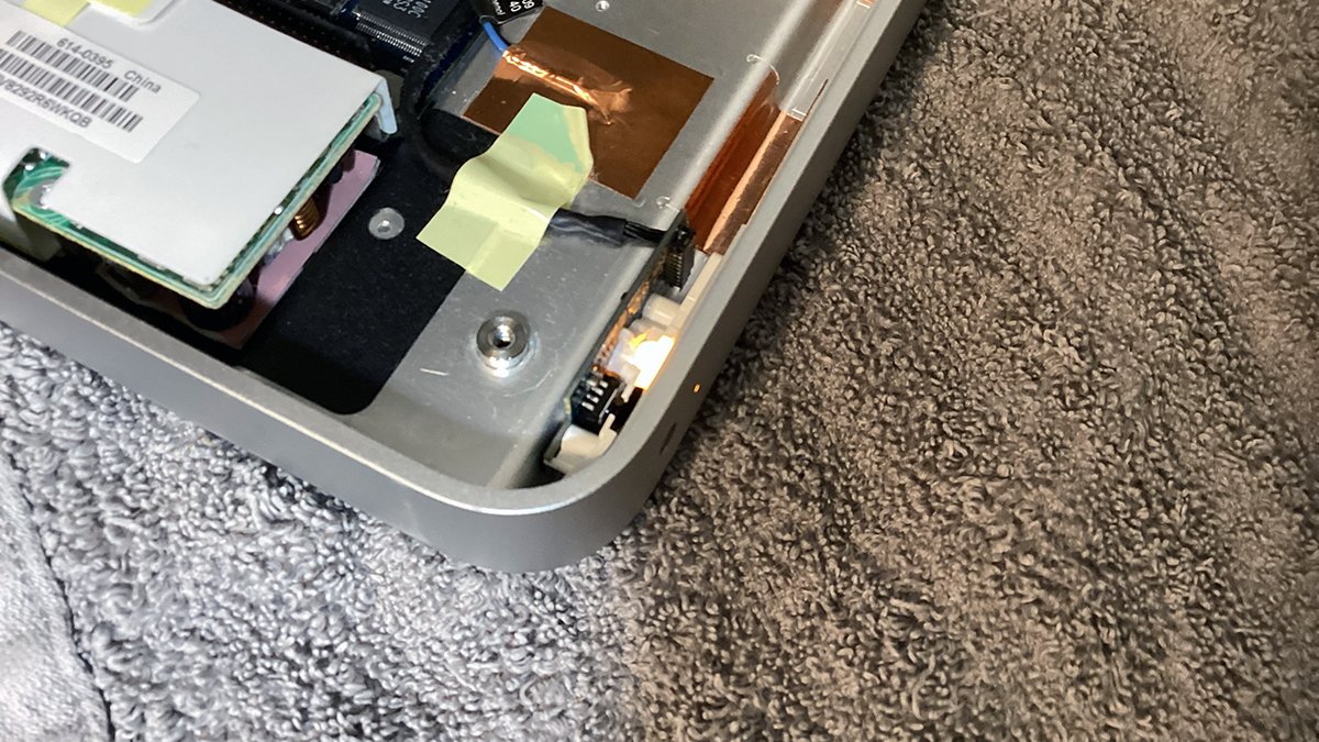 Testing power. Without the hard drive attached, you should get a steady blinking amber LED.
Step 5: Remove and clean fan
The Apple TV's fan is held in by three small plastic posts with clips a the tops. The clips snap into holes on the fan's edges, locking it in place. At this point, you'll need to decide if you want to risk damaging these posts in order to remove the fan.
After seventeen years, the plastic in these clips will be extremely brittle and prone to breaking. You can still reinstall and secure the fan using alternative methods later, but it's likely removing the fan will break at least one of them.
If you do decide to remove the fan, you'll need to squeeze the top of each post with small tweezers, then gently pull up on the corner of the fan to free it. Repeat this step for the other two posts until the fan is free.
You'll also need to disconnect the fan's wire connector on the motherboard. Be careful since this connector will be brittle too.
The fan doesn't actually cool anything directly. All the major chips are on the other side of the motherboard. There is a small bank of resistors and capacitors under the fan, and it keeps these parts cool since they power the chips on the other side.
Most of the heat on the motherboard is cooled via convection. The fan draws air across the board and sends it out to the heat conduit where it gets spread to the main frame and bottom plate.
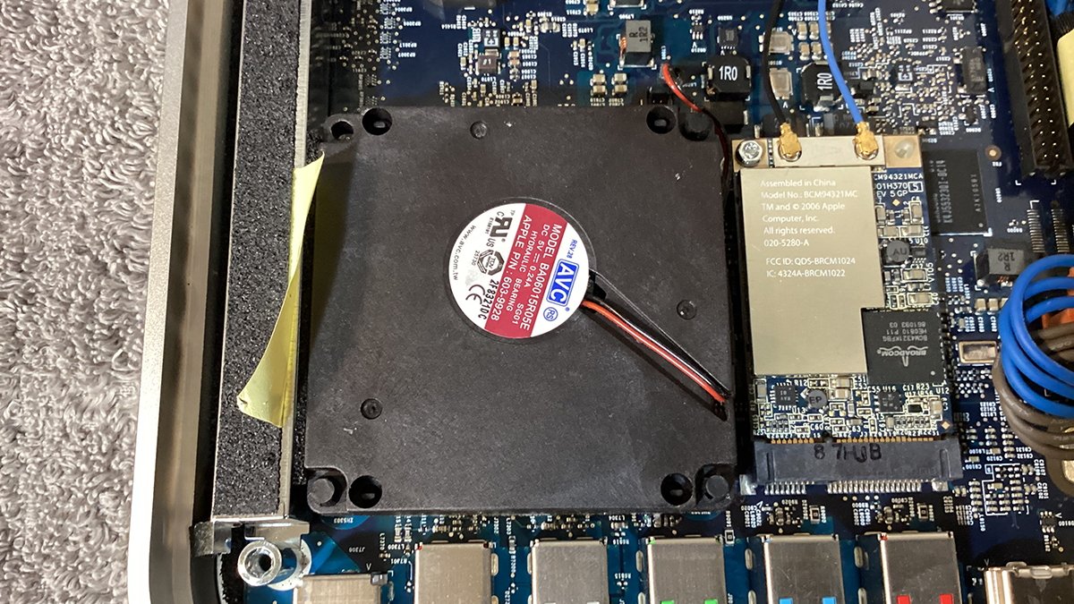 The main cooling fan. Note the posts on the three corners.
At this point, unless your Apple TV is very dirty inside, or the power supply isn't working, you're mostly done with disassembly. You'll want to use compressed air to blast any dust out of the fan, and from around the motherboard.
Unless you want to remove the motherboard you don't need to remove the WiFi card or power supply. You can use compressed air to clean the rest of the motherboard and from around the components.
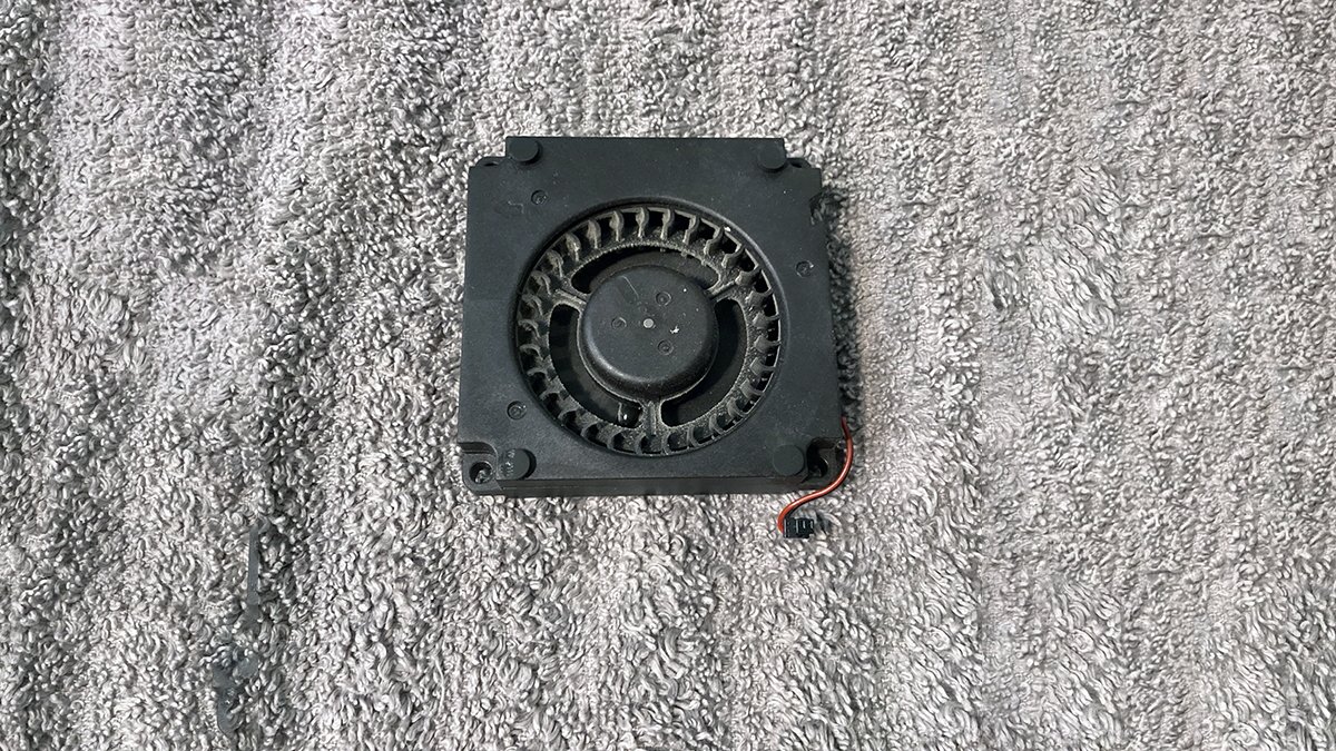 Fan removed and ready for cleaning. Ours was only slightly dirty.
Step 6 (Optional): Remove and clean power supply
If you do need to remove the power supply, proceed with caution. As we mentioned it can contain dangerous high voltage.
Always wear rubber gloves when handling the power supply, and never touch it while the device is plugged in.
This step should only be attempted by experienced users with knowledge of electronics and electricity. Proceed with caution.
If you merely want to clean the power supply of dust you don't need to remove it. Instead, just use compressed air around the ends and the small openings to blast any dust out of it
If your power supply doesn't work, you'll need to find a new replacement online and replace the entire unit.
This is fairly easy: to do so, remove the three Torx screws holding the power supply down, disconnect its connector from the motherboard, then slowly peel it up from its sticky insulating pad.
The insulating pad has strong adhesive on it and you'll need to carefully and slowly pry the power supply up from the pad to free it. Installation of a new power supply is the reverse of removal.
One reason Apple uses this kind of insulating pad to hold the power supply in place is to ensure no high voltages arc from the supply to the metal chassis of the device - which could pose a health hazard for users.
For this reason, don't remove the insulating pad from the device - you'll need it when you install the new power supply.
 Power supply removed. Note the adhesive insulating pad and the three mounting holes.
Power supply deep dive
Just for fun, let's take a look at the inside of the power supply. Ours is model ADP-36BF A from Delta Electronics of Taiwan, INPUT: 100-240V~1.0A 50-60Hz, OUTPUT: 5V @ 7.2A.
You can skip this section if you're not interested in the internal workings of the Apple TV power supply.
Most of the work of this supply involves taking the input 120V or 240V house AC current and stepping it down to 5V DC the device can use.
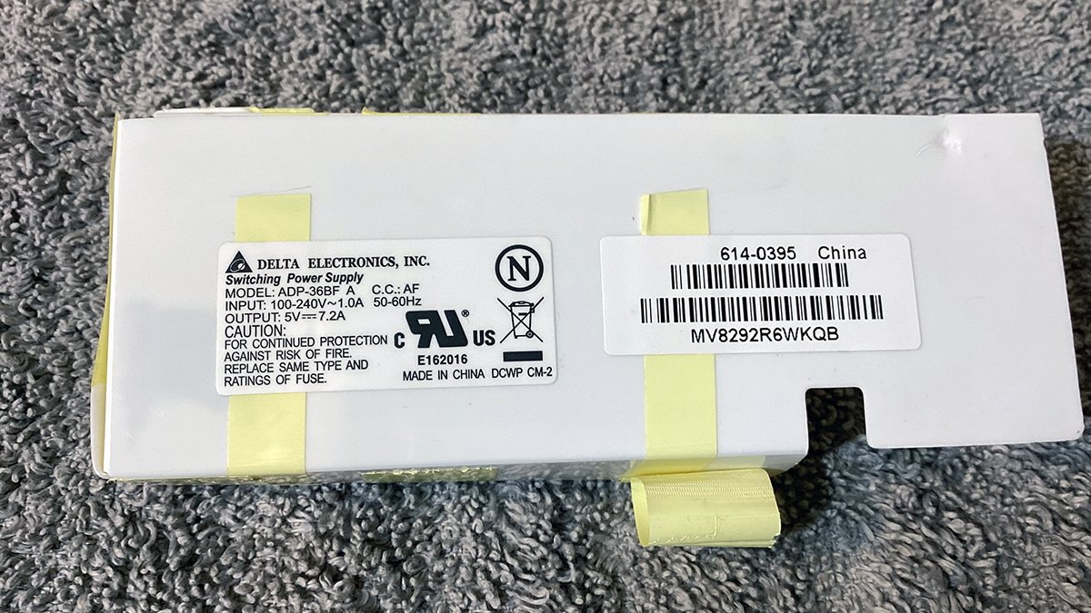 Apple TV 1st generation power supply from Delta Electronics.
To open the power supply (assuming you've confirmed it's fully discharged first), you'll need to remove its outer plastic cover. If you just unplugged the Apple TV wait a few hours before attempting this in order to give the capacitors time to discharge.
There are two small plastic clips on one side of the supply you'll need to remove with a hobby knife.
You'll also need to peel back three pieces of tape holding the plastic cover on. Once that's done you can carefully remove the cover.
You may need to score the tape in a few places to free the cover, but this can be re-taped later - or sealed with hot glue.
 You may need to score the tape in a few places.
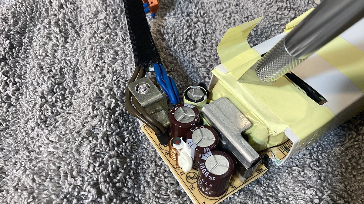
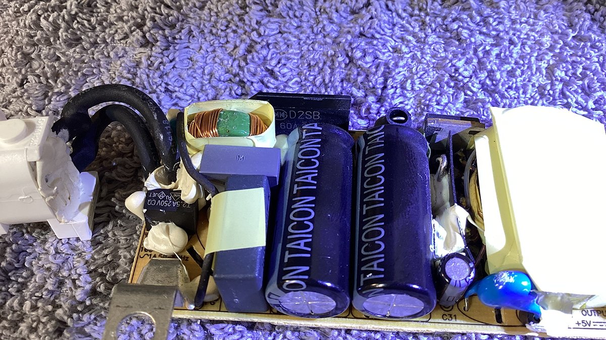
With the cover removed, we can see the power supply's components. From right to left in the photo below:
- Input
- 250V rectifier
- Two large EMI film caps
- Inductor
- High voltage ceramic cap (blue)
- Bridge rectifier
- Two large smoothing caps
- Smaller cap and high voltage ceramic cap
- STB10NK60Z 600V MOSFET transistor
- Large choke
- Three 10V output caps
- Output
 Apple TV 1st generation power supply with cover removed.
Briefly, the power supply works like this:
At input, the AC current is stabilized and filtered by the input rectifier and the two EMI film caps. These caps help remove any static or electromagnetic interference that may be in the building's electrical wiring.
Film caps are also known for being able to withstand high voltages without generating lots of heat. Many film caps found in personal computers dating all the way back to the 1980s are rated at 100V or more.
The coiled inductor then further stabilizes the current via an electromagnetic field. The purpose of most inductors is to store energy and resist any changes in current passing through them.
Next the current passes through the MOSFET transistor and the bridge rectifier. They are partly responsible for converting them to DC and stepping them down to a lower voltage, along with the large coiled choke to the left.
Chokes act somewhat like large resistors and they work by means of a large copper wire winding which provides resistance to current passing through it. Depending on the side of the coil, voltages can be either increased or decreased by either drawing more or less power on the opposite side.
They also block higher-frequency AC current while allowing lower-frequency AC and DC current to pass through. Common mode chokes are also used as part of EMI suppression.
MOSFETs are multi-use transistors that can act both as amplifiers and switches. MOSFETs can be used as gates that change the conductivity of the device based on the value of an input voltage at one of the device's terminals.
Next, power is stored in the power supply in the two large electrolytic caps to smooth it. Known as smoothing caps, these components act like small batteries and prevent any spikes or surges that may be present in the input circuit.
Bridge rectifiers or "diode bridges" are small packages that contain several diodes which prevent current from flowing in the opposite direction. They also handle converting AC current to DC current.
In this case, the power supply contains a D2SB bridge rectifier rated for 200V @ 1.5A.
Most bridge rectifiers work by converting the negative portion of the AC input to a positive voltage. They then smooth it to produce a single continuous DC current.
Some bridge rectifiers can handle two AC inputs and two DC outputs at the same time.
These components are often found in switching power supplies such as the ones found in Apple TV.
Bridge rectifiers were invented in the late 1800s and were a critical step necessary before integrated circuits could be produced.
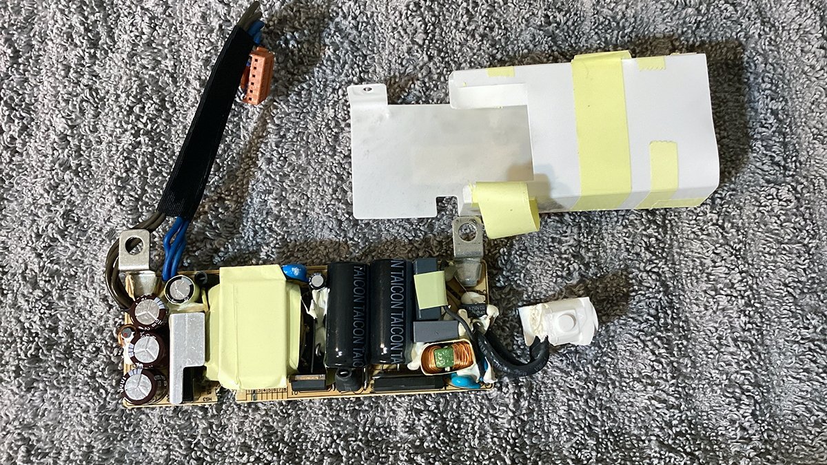
 Reverse view of the power supply. Note the D2SB bridge rectifier lurking at the center.
You may have noted a lot of hardened white putty around several of the power supply's components.
This putty is used to hold components in place so they don't touch, but it also acts as a high-voltage insulating material to prevent electrical arcing. This arcing could potentially short and destroy the power supply, cause fire, or injure users.
By sealing many of the high-voltage components in insulating putty the designers of the power supply can ensure no adverse effects or damage. For these reasons never remove any of the putty from the power supply - unless you have to in order to replace a component.
If you open the power supply, inspect all the electrolytic caps for leakage or bulging. When some electrolytic caps get old they start to bulge at the top along the metal disk and plastic wrapper.
If the metal disk on top of a cap looks swollen, or if it looks unusually wide with only a small amount of plastic around it, the cap may be bad.
When the electrolytic fluid leaks out of a cap it usually does so along the bottom around the connecting pins. So look for discoloration along the bottom edge or on the reverse side of the board.
Once you've cleaned or obtained a new power supply, you're ready to move on to the next step. To do so the power supply must be removed first.
If you opened your Apple TV's power supply and plan to keep it, reinstall the plastic cover and plastic snaps, and reseal the tape.
Step 7 (Optional): Remove and clean the motherboard
This step is also optional. If your Apple TV isn't very dirty this step isn't really necessary. Dirt and dust can collect under the motherboard and prevent airflow and heat dissipation.
If your Apple TV motherboard is very dirty you might want to clean under it.
To remove the motherboard, you'll first need to remove the WiFi card by removing its screw and wires, and then removing the heat conduit on the left side.
If you can't reach the recessed Torx screw through the hole in the top of the conduit, you can still remove it by slightly (and carefully) bending the top side to the right to allow access with a normal Torx driver.
If you do this, do so carefully, and don't bend it too much. The top of the conduit also acts as a support for the bottom cover so it has to sit evenly with the frame.
Once you remove both the conduit screws, lift the conduit out of the device.
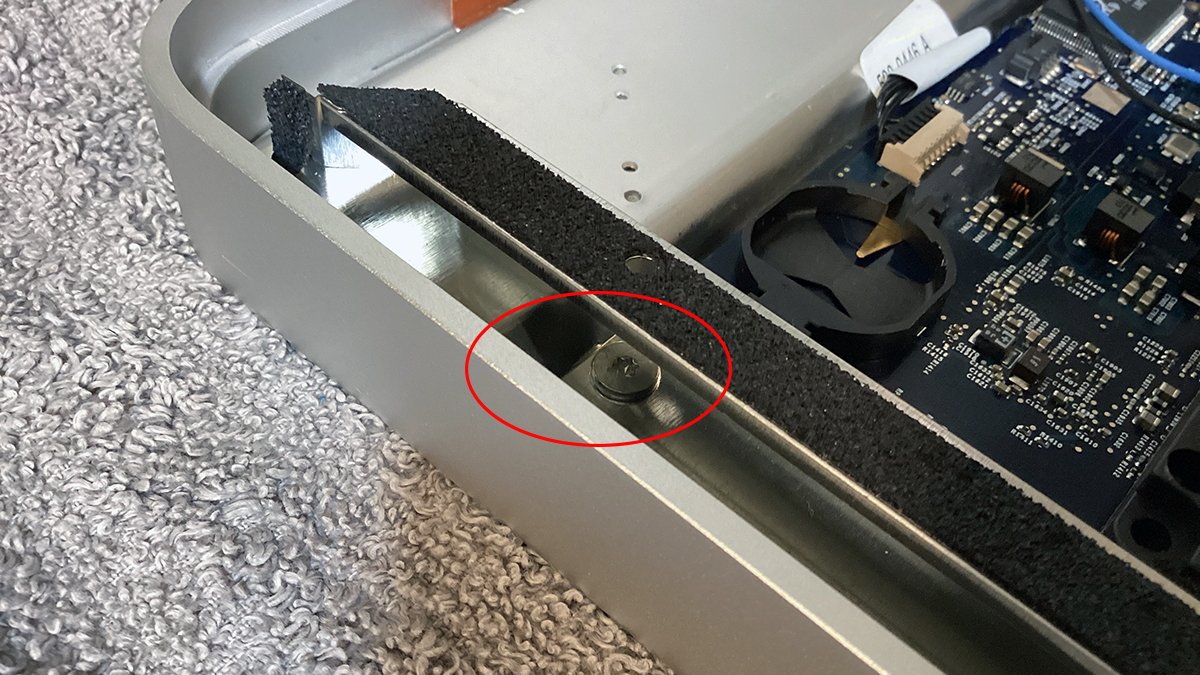 The hidden Torx screw under the heat conduit.
At this point, the motherboard is effectively free, but it's still being held into the frame by the ports at the back of the machine. To remove the motherboard, slide it forward and lift its front edge up and out.
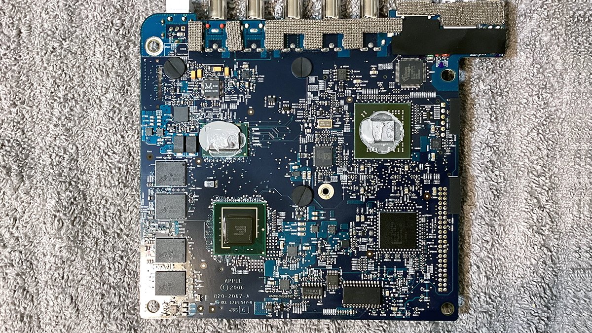
Once the motherboard is free, flip it over and inspect it for any damage, burn marks, corrosion or other inconsistencies.
Two of the chips on the bottom of the board have thermal paste on them. Unless it's extremely dried out and flaky, there's no real reason to remove and replace it. Try not to disturb it if you're not replacing it with new paste.
Re-installation and re-assembly of the motherboard is the reverse of removal.
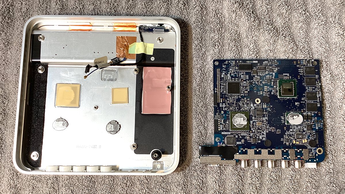 Motherboard removed with underside visible. The top case also has two stick-on thermal pads for the other two chips.
Step 8 (PhD-level extra-credit difficulty): Upgrade the RAM
This step is also optional. If you don't want to upgrade your Apple TV's RAM, skip this step (it's quite long and complex).
As mentioned, the first generation Apple TV only shipped with 256MB RAM. The architecture of the system allows for up to 1GB of RAM, but as many Apple TV modders have discovered, the real upper limit is 512MB.
This upgrade is extremely difficult and you risk damaging your Apple TV motherboard in the process.
The RAM upgrade isn't as easy as merely replacing chips. It also involves soldering bodge wires, removing the chipset controller (Intel G45U), removing, reprogramming and re-flashing the firmware ROM, and advanced SMD and hot air soldering skills.
To perform the RAM upgrade you'll also need special equipment and solder flux. This includes:
- SMD solder paste
- Hot air board preheat device
- Hot air soldering station
- Soldering iron
- Solder wick
- Fine enamel-coated wire
- Voltmeter
- Tweezers
- Optionally a microscope
- Four replacement 128GB DDR2 SMD RAM chips
You'll also need a USB EPROM programmer and a Windows computer to attach it to. The programmer must also include the correct adapters to fit the small SMD ROM chip you'll need to de-solder and modify.
You perform this step by de-soldering the ROM, placing it in the USB programmer, dumping its ROM code to a Windows machine, patching the code for larger RAM chips, then flashing the modified ROM back to the chip and re-soldering it.
Worse, the higher-density RAM chips have different memory lanes and some of the RAM connection points on the Apple TV motherboard aren't connected to anything.
This means you'll have to solder additional bodge wires onto the chip pads. You'd also have to de-solder and re-solder the integrated Intel chipset controller to connect the additional RAM lines.
All of this is a daunting task and if you're not 100% certain of your skills, don't do it - it's too easy to destroy the motherboard or components in the blink of an eye.
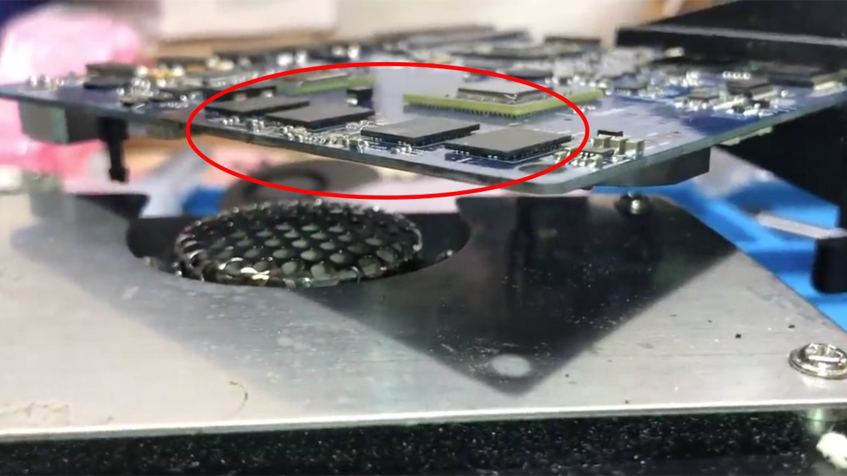
As in several late-model Macs, the RAM is soldered to the Apple TV motherboard as surface-mount devices (SMD). These devices are flat and have a solder-ball matrix on their undersides.
There are no through-hole or edge connectors and these RAM devices can only be soldered on with hot air.
Removing and re-soldering these devices involves heating the motherboard with hot air to remove the parts, then melting the old solder, applying flux and adding new solder. After that, you place the new components and attach them to the motherboard with hot air.
As the solder heats up, each device is automatically drawn into place on the solder grid on the motherboard. When hot air is removed, the solder hardens securing each part in place.
It's really easy to mess this kind of repair up and render the computer un-bootable. Hence, only attempt this step if you are fully confident in your SMD soldering skills.
A close-up view of the underside of the Apple TV motherboard reveals four 64MB RAM devices along the left side for a total of 256MB of RAM. The original RAM chips are made by Micron and are DDR2:
 Four DDR2 RAM devices along the left side of the bottom of the motherboard.
To get started place the motherboard face down on a hot-air SMD preheating device. You don't want to use an "oven" style PCB preheater to heat the board - you want the kind which blows hot air out of the top to evenly heat the board under the spot its laid on.
One example of such a preheater is the Hakko FR830-02 from Japan, but it's really expensive (close to $400).
The preheater keeps the motherboard at an elevated temperature so that when you hit the RAM chips with your hot air-station, they come right off without too much time.
Next, apply extra flux to the edges of the RAM chips remove all four chips with your hot air soldering station and a pair of tweezers.
Apply extra flux to the pads where the RAM chips were soldered to the motherboard, heat them, and then remove any excess solder from the pads with a solder wick.
Also using the preheater and your hot air station, remove the firmware ROM chip on the front-side of the motherboard. Depending on which motherboard you have, the size and location of this chip may vary.
Usually, it's a 14-pin or 8-pin SMD device near the top edge of the motherboard. You'll need to de-solder it, clean it, and place it in a correctly-sized EPROM adapter.
For some EPROM programmers, you'll need to first solder the ROM chip onto another adapter board which then gets inserted into the programmer.
Now plug the adapter into the EPROM USB programmer and plug the programmer into your Windows computer. Using the software that came with your EPROM programmer, copy the contents of the ROM to a file and save the file to disk.
You'll later modify this ROM file by patching a section of it and re-flashing it back to the ROM chip using the programmer. This step allows you to tell the firmware what size RAM the computer has.
Finally, remove all the extra flux from the RAM solder pads using a paper towel and isopropyl alcohol.
 The four RAM chips soldered to the motherboard atop the hot air preheater. Note the solder balls under the chips. Courtesy dosdude1.
Note the layout of each matrix on the motherboard where the RAM chips were. These pads connect parts of each RAM chip with different parts of the computer.
You can look up the solder matrix on Micron's RAM website to see what each pad is used for.
Some of the solder pads connect the address lines of each RAM chip to the chipset controller which accesses their data via these connections. Unfortunately, the larger-sized RAM chips require additional access (address line thirteen) to work which Apple didn't anticipate using.
So some of the pads required for larger chips aren't connected to anything on the Apple TV motherboard. Because of this unfortunate oversight, you'll need to connect those RAM lines yourself using bodge wires.
And you'll need to do this for each of the four RAM chips.
A bodge wire is simply an additional extra wire used in electronics to connect something that wasn't intended to be connected, or to bypass circuits on a board to rewire connections.
You also need to connect each of the bodge wires connected to the correct pin on the controller chip to a spare unused pin on a pullup resistor on the motherboard in order to connect each to the DDR2 power rail.
All of the bodge wires on all four RAM chips connect the same thing since they're all part of the same RAM bank.
In this case, the bodge wires will connect the additional address line to the chipset controller directly. But first, you'll need to modify the ROM's SPD data for the new memory chips and reflash the ROM.
To do so, open the ROM file you dumped above in a Windows hex editor and search for the string "80 08 08 0D 0A". This is the header for the SPD data in the ROM file.
Each byte in the string tells the firmware about the characteristics of the RAM installed on the motherboard.
You'll need to dump the 256 bytes following this string to a file. Then you will have to open it in a Windows app called SPDTool which allows you to view the SPD data in a UI, changes its values, then save it back to a file.
Once you've modified and saved the file, you can dump that data back to the original data in the ROM file. This overwrites it and thus updating the SPD data which tells the Apple TV firmware what kind of RAM is in the machine.
If all this sounds confusing, it is. But luckily legendary retro YouTuber dosdude1 has a video detailing the entire RAM replacement and firmware editing process.
He also explains the differences in the memory lanes between the two different size RAM chips, and how to do the bodge wire soldering to bypass the RAM connection limitations on the Apple TV motherboard.
Once you've updated and re-flashed your Apple TV ROM with the new SPD data, apply some new solder paste flux to its pads on the motherboard. Use it to re-solder the ROM back onto the motherboard using a hot air station.
Clean the ROM area with isopropyl alcohol and a cotton swab.
Before you actually attach the bodge wires, you'll need to remove the Intel G45U controller chip using hot air, "reball" it (reflow its solder balls on the underside using hot air), and clean off any left over flux.
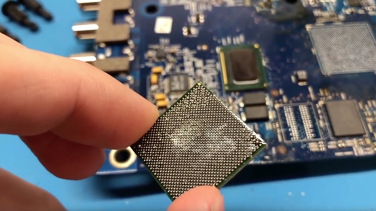 Intel G45 controller chip. Notice the solder-ball matrix on the underside. Courtesy dosdude1.
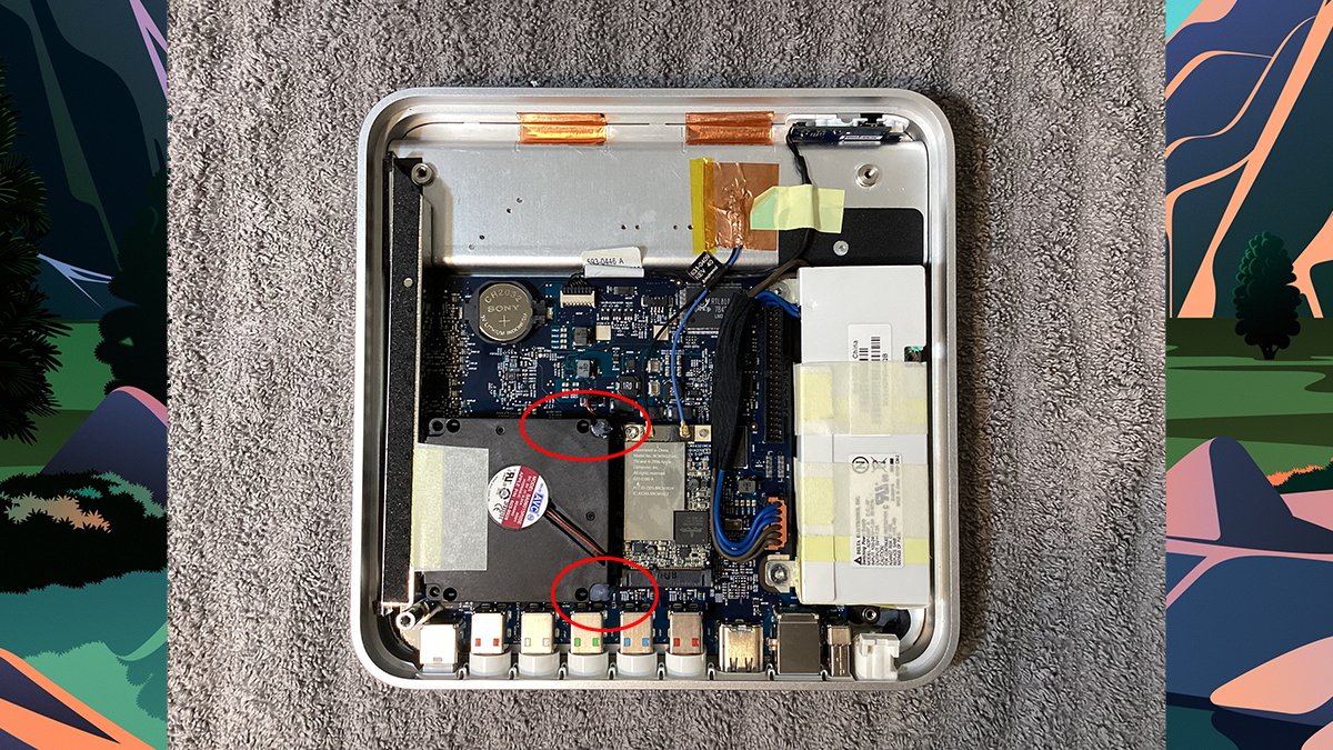
You'll need to connect a bodge wire from pin seven on the G45 chip to the pad for address line thirteen on the first of the RAM chips.
It turns out Apple provided a via - a pass-through hole to the other side of the board on pin seven on the bottom row of the G45 chip on the motherboard (the G45 pin row closest to the RAM chips).
On the topside of the board, this via attaches to a testpoint not far from the coin-cell battery holder. This means you can connect the bodge wire from address line thirteen on the first RAM chip to the testpoint on the topside of the board and not have to mess with soldering the wire to the G45 chip itself.
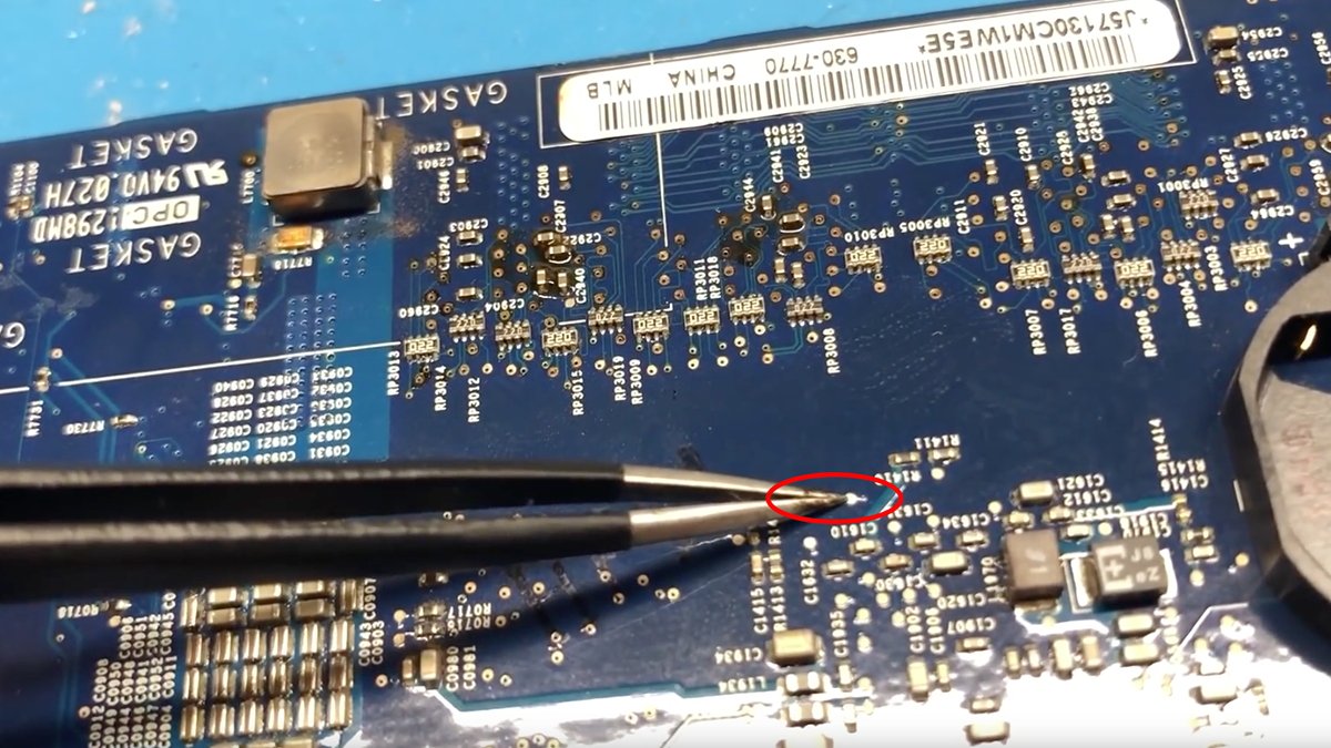 The topside testpoint near the coin-cell holder which attaches to pin seven on the G45 chip on the other side of the motherboard. Courtesy dosdude1.
You'll also need to solder another bodge wire from the fourth RAM chip's address line thirteen to the spare pullup resistor pin on the underside of the board for DDR2 power. This resistor is just below the RAM chips.
Do this step after the G45 chip has been reballed and resoldered to the motherboard
Next, solder a bodge wire from each of the RAM pads for address line thirteen to the adjacent RAM chip's address line thirteen pad. On each chip this is the lower bottom right pin in each solder matrix.
You want to connect all four address line thirteen pins together with wire.
By soldering all these pins together with wires you complete the circuit for address line thirteen so the G45 chip can access the new RAM fully. This is by far the most difficult step in the RAM upgrade.
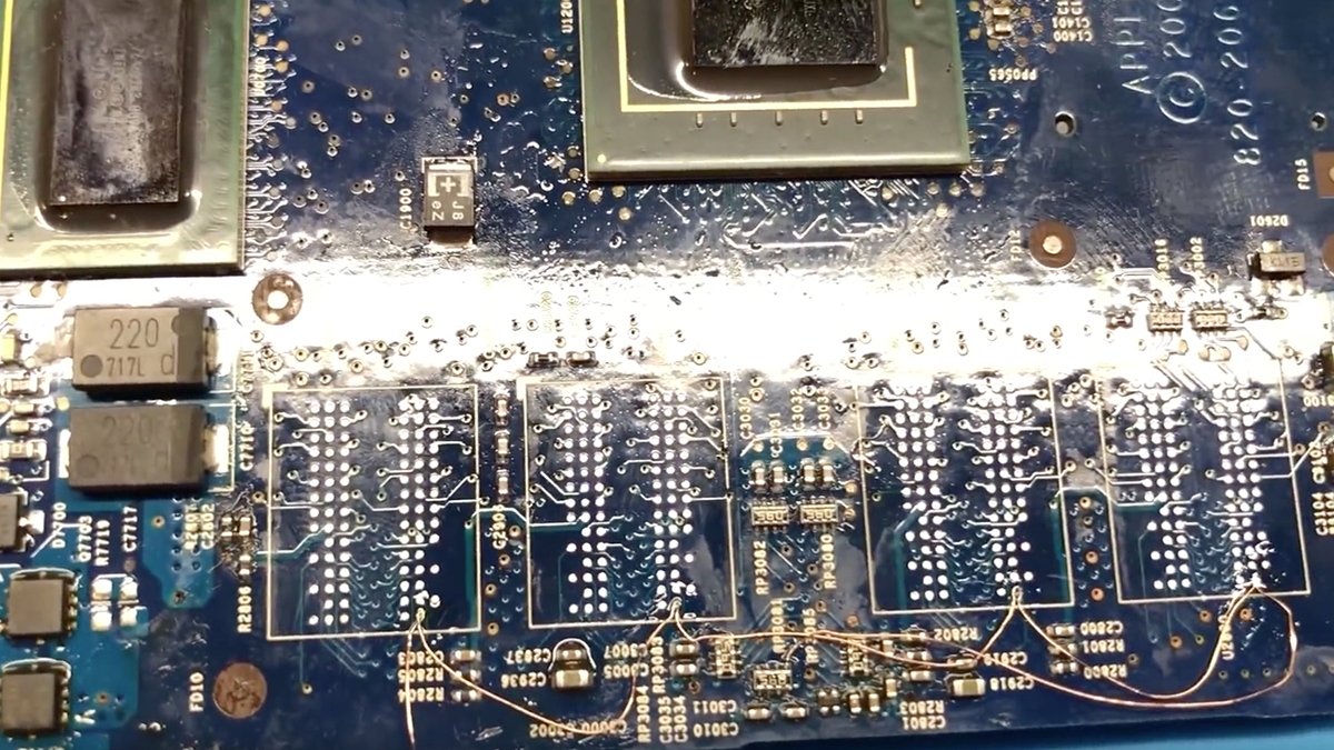 Bodge wire installation - bridging address line thirteen on all RAM chips, to the pullup resistor, and finally on the left to the topside of the board.
Finally as the last step, solder all four new RAM chips onto their pads on the motherboard using hot air after adding new flux to the chip pads - making sure none of the bodge wires move or come loose.
Clean any excess flux from the area with isopropyl alcohol (carefully so you don't pull the bodge wires loose). Finally, reinstall the motherboard back into the Apple TV chassis, reinstall the heat conduit, and the WiFi card.
You may want to cover the bodge wire area with wide Kapton tape just to insure none of the connections can short to the chassis or to the motherboard.
Reattach the WiFi card antennae wires, then reinstall the power supply after all the motherboard parts are secured to the Apple TV.
Step 9: Reinstall the fan and close the case
Now that most of the Apple TV is back together, you still need to reinstall the fan.
If one or more of the plastic posts holding the fan in broke when you removed it, fear not. Drop the fan back in place on its posts, and if the tops of any of the posts broke off, simply add a large drop of hot glue with a glue gun to the top of the posts.
If you don't have a glue gun, a small amount of waterproof bathroom caulking will work. Use just enough to cover the top of each broken post, and let it dry.
This should securely hold the fan on. In our refurb we lost two of the three post clips when removing them but hot glue worked just fine after replacing the fan:
 Fan reinstalled with hot glue used on the two posts on the right.
Don't forget to reconnect the fan connector to the motherboard.
Finally, plug the ATA drive's ribbon connector back into the ATA connector on the motherboard, and replace and secure the bottom cover with the four corner Torx screws. This completes the repair.
Remove any excess glue from the bottom of the cover. You don't need to remove all of it but remove any that sticks up even a little since it will prevent the bottom rubber foot from laying flat on the cover.
What kind of glue to use to reseal the bottom foot is up to you. Do not use rubber cement. It's not strong enough and the chemicals in it cause the rubber foot to curl up making it impossible to re-secure it.
We used small amounts of Tacky Glue from Fabrique Pour (aleenes.com).
You may not need to cover the entire bottom of the cover with glue to re-attach the foot. A small amount in the corners and in the middle may suffice. Try it and see.
Set a heavy object such as a large book or weight on the foot until the glue dries to make sure it sticks evenly.
Step 10: Reinstall the OS
If you upgraded the Apple TV's hard drive, or wiped it while it was disconnected, you'll need to reinstall the operating system.
To do so, use a tool called OpenELEC and a USB thumb drive. You'll also need a Mac drive flasher utility such as BalenaEtcher to flash the factory restore installer image onto your USB thumb drive.
The original infrared remote control included with the 1st generation Apple TV is also required. This is needed because holding down a special key combination on the remote tells the Apple TV to boot from the USB port instead of from the internal hard drive. More on this below.
The website tweaking4all.com has detailed instructions on how to use OpenELEC to reinstall the OS.
Also see this page on Apple's discussion forums.
Essentially the process involves downloading the 3.0.2 restore image for Apple TV (factoryrestore-3.0.2.img.zip) flashing it to a USB thumb drive, inserting the drive into the Apple TV's rear USB port, then rebooting the Apple TV.
Unzipping the above file yields an image file named "factoryrestore3.img". Use BalenaEtcher to flash this image file to a USB thumb drive. Be aware doing so will erase everything previously on the thumb drive.
After the flashing completes, the Mac Finder will give you an error saying the USB drive is unreadable. Click Eject then remove the USB thumb drive from your Mac.
Plug the newly flashed USB drive into your Apple TV, plug it into an HDMI TV and a wall outlet, then power it on. As soon as you see the amber flashing LED on the front of the Apple TV, hold down MENU and the + buttons on the remote control.
As soon as you see an activity light on the USB thumb drive, release the two buttons on the remote.
Shortly you'll see the OpenELEC app load:
 OpenELEC boot sequence on Apple TV.
There's no interaction onscreen with OpenELEC - once it loads it wipes the Apple TV internal drive and begins restoring the Apple TV OS to it. After it finishes, OpenELEC will reboot your Apple TV, dropping it into the default Recovery mode.
Use the remote to scroll down to Factory Restore and click the center button on the remote to confirm. Apple TV will reboot and go into full restore mode to restore the device to factory conditions.
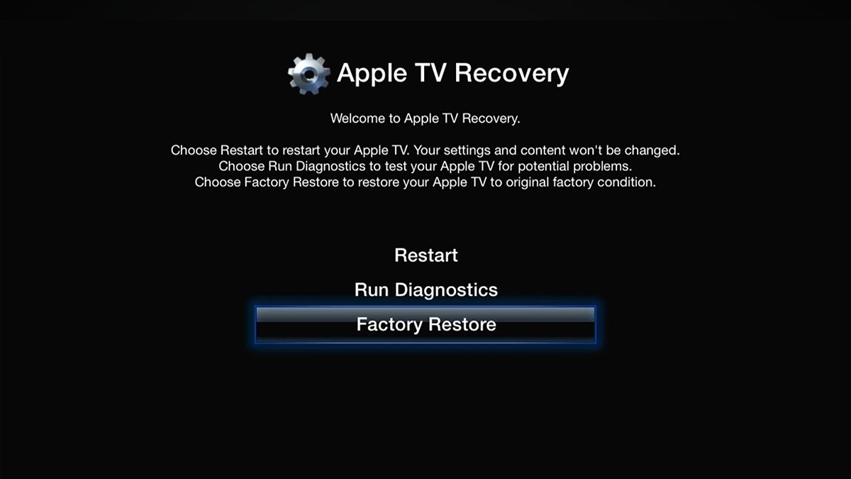 Apple TV Recovery mode. Scroll down and click "Factory Restore" then press the center button on the remote.
After TV Recovery mode does its thing, the Apple TV will reboot again, and this time you'll be thrown into the default factory setup sequence. You'll see a bit of animation followed by a few setup screens.
Enter your info to set up your Apple TV. Once setup is complete, you'll be at the main menu prompt without any content:
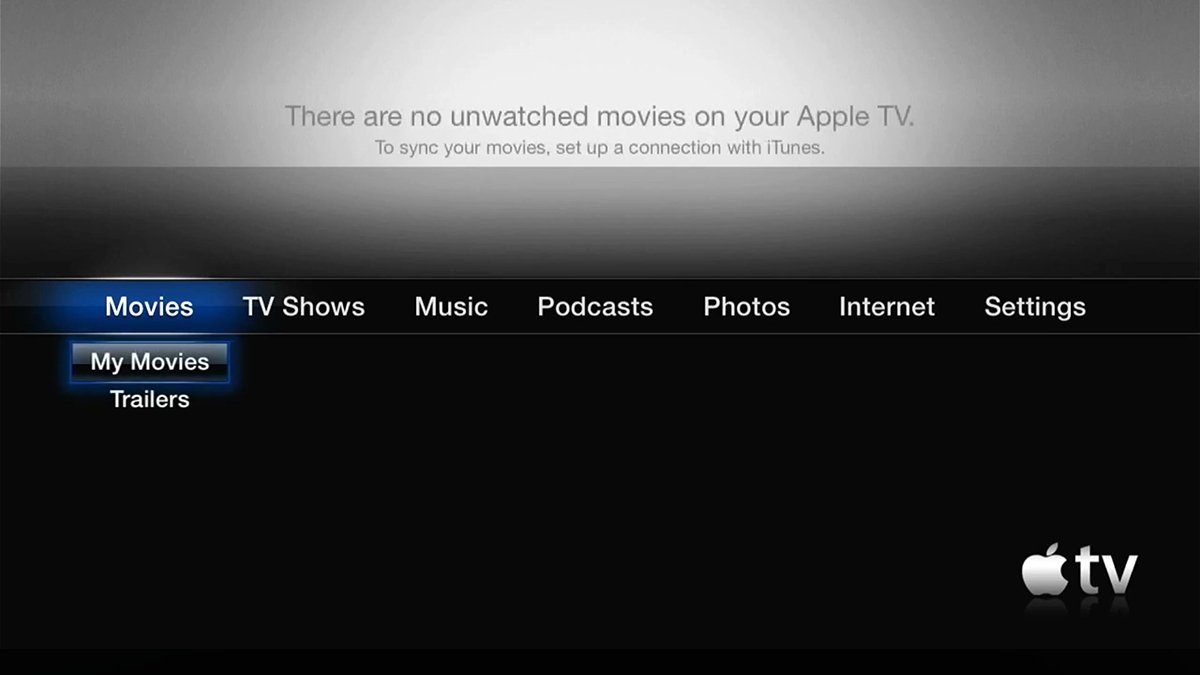 Apple TV 1st generation main menu.
Step 11: Connect to iTunes
As we mentioned previously there is no App Store for the first generation Apple TV. To upload content to your Apple TV you'll need to connect it to an older Mac or Windows 7 computer and run Apple's iTunes app - the predecessor of today's Apple Music app.
In iTunes you can connect to your Apple TV and sync any media content to it you want to play. To do this, run iTunes, select your Apple TV in its sidebar, then select what media to sync in the righthand pane and click Sync.
You may be asked to enter a code displayed on your Apple TV's display in iTunes in order to connect.
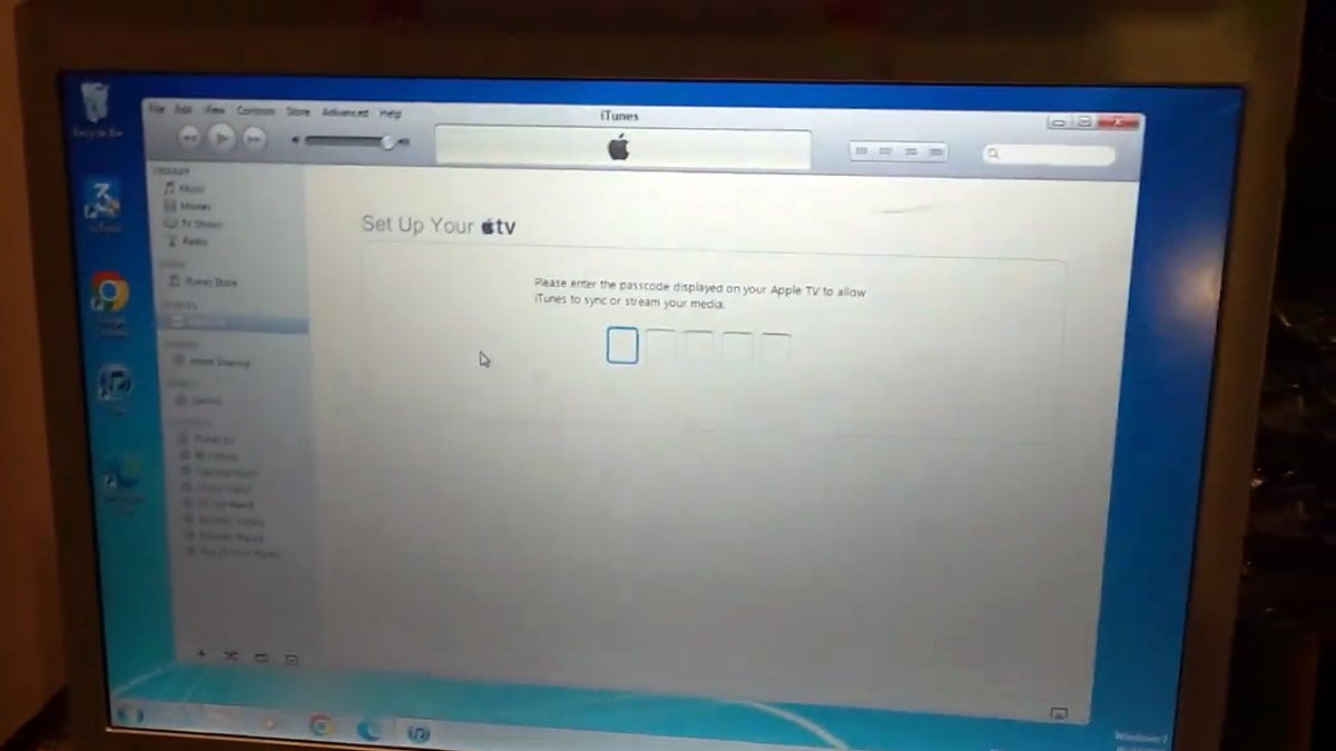 Connecting in Apple's iTunes on Windows 7. Courtesy dosdude1.
The original Apple TV was a revolutionary device for its time and even though it didn't have access to an app store, it was still useful. You can still use these devices for photo albums, music, movies, or if you need to run older apps.
The first-generation Apple TV was soon replaced with the more modern models we know and love today.
Quartz has a page titled A visual history of Apple's TV products.
Also be sure to check out Dave Murray's YouTube video Hacking the Apple TV 1st Generation from nine years ago, and Apple TV First Generation Disassembly for repair or upgrade from 1000uF.
Steve Jobs once called the Apple TV "Our hobby" but it has evolved into much more than that - and it will likely be with us for a long time to come.


-m.jpg)


 Charles Martin
 Mike Wuerthele
 Marko Zivkovic
 Malcolm Owen


 William Gallagher
 Amber Neely


-m.jpg)


7 Comments
From a purely aesthetic point of view this is the best AppleTV Apple has ever made. And an HDD drive, for the purpose of streaming and storing files locally (like pictures and so on) is perfect.
I wish Apple would release an AppleTV which is much more the true center of the home instead of basically a streaming box. Even if the device has to get bigger do accomodate a better CPU (which can handle Apple Intelligence) and a decent amount of local memory. It could really become a gaming device, the center of your home and still be the best streaming device there is. AppleTV has had so much unexpressed potential.BTW. I owned the original one. It was a beauty.
I think I still have my original ATV in a storage bin. It was kind of a flakey device in terms of functionality (heat issues, lots of crashing/freezing) but I still really enjoyed using it due to it being so unique to the market at that time.
Great detailed tech article. Thank you.
Great to read Chip. I love the detail of bodging an extra address line. Gotta ask, why though? 😂
Enjoyed this article just like I often enjoy iFixit guides - it's fun to see how things are made and what you can do to improve and/or repair them! I don't think I'll be buying an original AppleTV for myself, though.