In a previous article, we looked at connecting various kinds of Arduino hardware to your Mac. Here's how to get started programming on them to create your own projects.
Getting started
In order to program your Arduino, you need the Arduino IDE (Integrated Development Environment) from the arduino.cc website. We mentioned how to download and install the IDE in the previous article but we'll reiterate it here:
On your Mac, go to arduino.cc, click on "Software", then under the Download Options section, click the link for the Mac version for either Intel or Apple Silicon.
Note that unless you want to explore the current development version, you don't want the link under the section "Nightly Builds". Nightly builds may be unstable and contain bugs.
The downloads page also links to the Arduino online Web Editor, which allows you to save your programs to Arduino's cloud.
Once you've downloaded the IDE, refer to the previous article for details about how to connect and set up your Arduino on your Mac in the IDE. You need a connection before you can upload code from the IDE to your Arduino.
Basics
You only need rudimentary programming skills to program your Arduino. You can use Arduino's C-like programming language, or Python, but we'll only use C in the examples below.
In Arduino programs, called Sketches, you essentially write code to set up your Arduino for a specific tasks or tasks, then run a continuous loop which gets called repeatedly by the Arduino microcontroller once your Sketch is uploaded to your Arduino device. The loop usually waits for input from sensors or users, and sends control signals back to sensors and devices to display some sort of output.
The loop code can also connect to, and interact with, the internet.
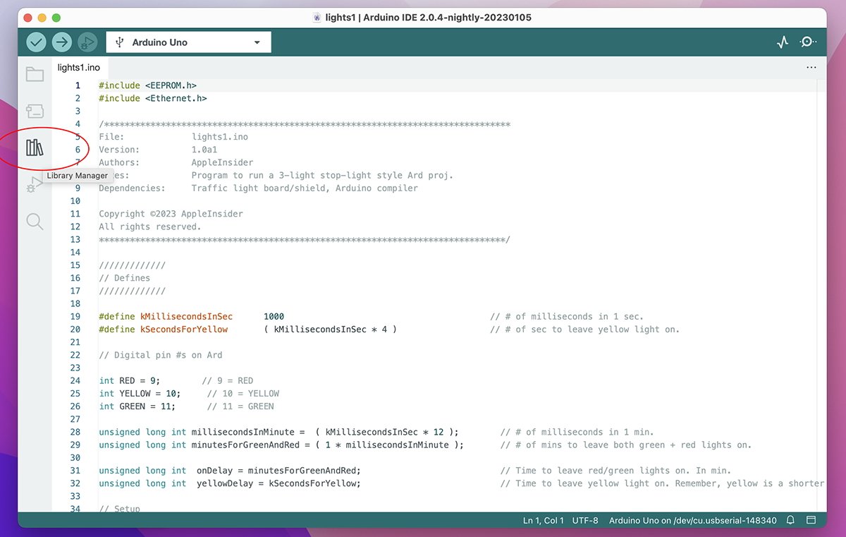
You can also install third-party libraries which support various sensor devices and shields using the Library Manager in the IDE. To access the Library Manager, create or open a sketch window, and click the icon on the left side which looks like a set of books:
A pane will appear and at the top, you can browse available libraries by Type and Topic by clicking either of the two popup menus:
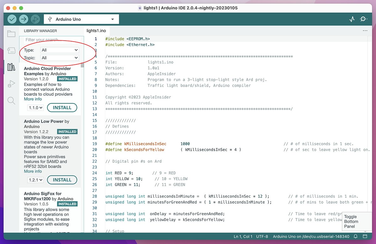
You can also check for installed library updates by selecting "Updatable" from the "Type:" menu.
The Library Manager pane lets you download official and third-party libraries. Libraries are code bundles that add a specific functionality or device support to the IDE.
For example, if you use a particular brand of a non-generic sensor, you'll need to download its library and install it first.
You can view different categories of libraries by clicking the "Topic" popup menu at the top of the Library Manager window.
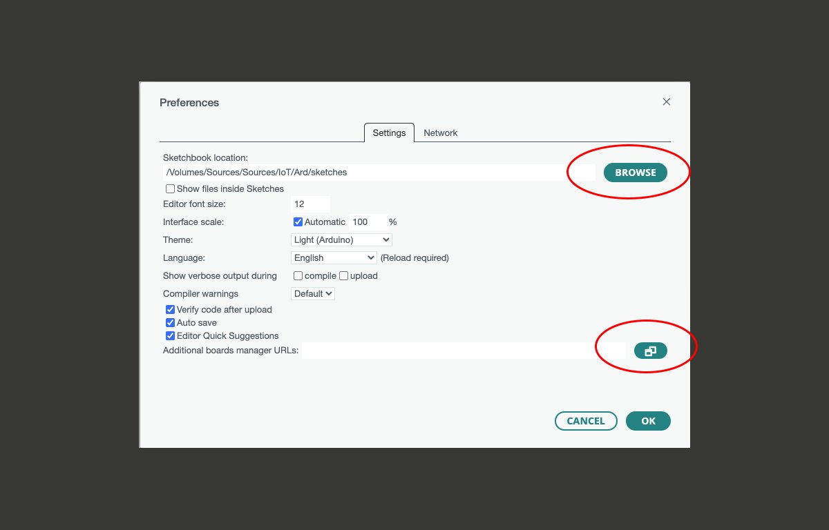
Most Arduino Sketches are simple and short and are stored in a "Sketchbook" folder specified in the Arduino IDE Settings window. You can change where the IDE stores sketches from here by clicking the Browse button next to "Sketchbook location":
Sketches have a file extension of .ino, which stands for "innovation".
You can also change text editor and compiler settings here. If you have an unsupported Arduino, you can add its board support file or URL by clicking the small icon in the lower right of the window, one which looks like a stack of documents.
Click on the "Click for a list of unofficial board support URLs" text in the Additional Boards Manager URLs window to view the vast array of boards supported on Arduino's GitHub.
The Arduino IDE provides a sample sketch with a simple program outline in a text window when you first open it.
There are also a vast array of code samples under the File->Examples submenu item. Samples are organized by "Built-In" and "UNO Examples" in the menu. Custom-installed libraries may also provide examples.
A first example sketch
In our first example, we'll use the built-in Blink example. To open it, select File->Examples->0.1Basics->Blink submenu item.
After a few seconds, a new editor window will open with the Blink example. Make sure your Arduino board and port are selected from the connection popup menu at the top of the IDE's editor window.
Blink does one thing — it blinks a built-in LED on the Arduino. There's a description of the sample in the comment at the top of the editor window and online.
In code, comments are notes programmers leave to describe what code is doing. Comments are ignored during compilation.
The IDE editor window uses C-style comments: the compiler will ignore anything bracketed inside of /* and */. Single-line comments start with // but must be on one line only. Anything after the // is ignored.
When you click the large Verify button with the checkmark icon in the editor's upper left corner, the IDE will compile the code in that window.
During compilation, an Output pane will appear at the bottom of the editor window in black showing progress. If there are no errors, you'll see messages such as:
"Sketch uses 924 bytes (2%) of program storage space. Maximum is 32256 bytes. Global variables use 9 bytes (0%) of dynamic memory, leaving 2039 bytes for local variables. Maximum is 2048 bytes."
Or something similar.
If there are errors, they will appear in red text and you'll have to fix your code until there are no more errors. Some errors are not critical, and your sketch will still run with them, but other errors can prevent your sketch from running at all.
You can clear the Output messages by clicking the small icon in the upper right corner of the Output pane. You can hide the Output pane entirely by clicking the small square icon in the lower right corner of the editor window.
When you click the Upload button (the one with a large right arrow icon) next to the Verify button, the IDE uploads the compiled binary program into the Arduino on the port you specified. The Arduino microcontroller takes over from there and executes your code on the Arduino.
During upload, if your Arduino has an RX (Receive) LED built-in, you should see it flash rapidly as it receives the sketch data.
If your Sketch couldn't be uploaded for any reason, the Output pane will list a description and why.
A few words about C-based languages
C was invented at Bell Labs in 1969 by Brian Kerhinigan, Dennis Ritchie, and Ken Thompson. Compiled C is blazingly fast, and most TCP/IP network stacks and operating system kernels are written in C.
There is also an ISO standard for C: ISO/IEC 9899:2018
C is the language of operating systems. Some early Mac apps in the late 1980s and the 1990s were written in C or one of its later variants: C++.
The Arduino IDE programming language is based on C-like syntax.
In most C-like languages, all code lines end with a ";" — without the semicolon, the code won't compile and you'll get an error.
Most C-based languages also use predefined code text files called headers, which usually have a ".h" file extension.
Think of a .h file as a predefined set of code that describes how functions are to be accessed, called prototypes. Each prototype defines a function name, parameters to be passed to the function (inside parenthesis), and a return type that is sent back from the function when it exits.
If you call (access) any library or built-in functions in your Sketch code, how you call each function must match its prototype defined in a .h file somewhere. Libraries work the same way.
For example, if a prototype says a function must take two input parameters (in the parenthesis), and a certain type of return value (listed before the function name), then you must call it in precisely the same way. Anything else will throw an error during compilation.
Header files can also contain a C-style construct called a 'define.' A define creates a label as another code expression, such as a number, text (a string in C), a calculation, or some other function.
To create a define, you use the #define C preprocessor directive. For example:
#define FALLING 2
This code defines the label 'FALLING' as the value of 2. Anywhere you use FALLING in your code, the number 2 will be substituted at compile time. #defines can get quite complex but can make your code shorter and more readable.
The Arduino IDE uses #defines to define things like I/O pin numbers, modes, and other things.
You can also create your own headers and #defines.
Headers can be included in other files - in other .h files, or in Sketches themselves. The contents each included .h file get inserted at compile time into the top of any files they are included in.
To insert a header into another file, use the #include C directive. For example at the top of Arduino.h you'll see:
#include "binary.h"
Which includes another header file called "binary.h" into the top of Arduino.h at compile time.
If you look at the screenshot shown above you'll see two included .h files in the example Sketch:
EEPROM.h Ethernet.h
All this may seem confusing at first, but it's actually quite simple: you put function prototypes and #defines in .h files so they can be used in many other files. Then you #include them in other files and the compiler inserts them where indicated during compilation. Easy.
Organizing definitions into seperate headers enables code reuse.
Just think of .h files as definitions, and your Sketch files as programs that use them.
Modern programming languages such as Apple's Swift and Microsoft's C# have done away with header files, in the interest of simplicity.
Back to the Blink example
In the Blink sample's setup() function, there is one line of code:
pinMode(LED_BUILTIN, OUTPUT);
Both LED_BUILTIN and OUTPUT are #defines defined by Arduino headers. The main Arduino header file is named Arduino.h, as we saw above.
You can hold down the Command key on your Mac keyboard and double-click any #define in an editor window to jump to its definition in the corresponding .h file where it's defined. A new tab will open in the same editor window displaying the matching .h file.
LED_BUILTIN is defined as "13" in pins_arduino.h:
#define LED_BUILTIN 13
This indicates digital pin 13 on the Arduino's pins connector (also called a header).
But at the same time LED_BUILTIN tells the Arduino to use the actual built-in LED on the Arduino circuit board itself. If you connect a jumper wire to pin D13 on the Arduino header, then connect it to an LED on a breadboard, it will blink that LED also.
pinMode' is a built-in Arduino function that sets how a given I/O pin on the Arduino behaves - either input or output. In this case, we're telling the Arduino to use pin LED_BUILTIN (13) as an output pin.
Since pinMode()'s prototype in the wiring_digital.h header has a return type of 'void', the function doesn't return any value. 'void' is a C data type meaning 'nothing'. All C functions having a 'void' return type return nothing.
When the compiled Blink sketch runs on your Arduino, it runs setup() first, setting up the hardware, then it runs loop() over and over forever. In the Blink example, loop() simply turns the pin on and off with a delay of one second between each:
digitalWrite(LED_BUILTIN, HIGH); // turn the LED on (HIGH is the voltage level) delay(1000); digitalWrite(LED_BUILTIN, LOW); // turn the LED off by making the voltage LOW delay(1000);
"High" and "Low in electrical engineering terms simply mean "on" and "off".
digitalWrite() is a built-in Arduino function that simply turns the digital U/O pin specified on or off - in this case whatever is attached Arduino pin D13, or LED_BUILTIN.
delay() is a delay function that halts further processing until the specified interval has elapsed. delay() takes a single time value, in milliseconds, with a value of '1000' being one second.
Go ahead and click the Upload button in the Blink Sketch IDE window.
That's it. You've now compiled and run your first sketch. If everything worked, you will see the built-in LED on your Arduino blink on and off.
Most shields also have a built-in LED on them which does the same thing as the built-in one on the Arduino.
A breadboard example
Now that you've seen the Blink example in action, we'll do the same thing - but this time we'll make an external LED on a breadboard blink at the same time. For this example you'll need:
First, plug two jumper wires into the "D13" or "13" and "GND" holes on the corresponding Arduino headers.
Plug the other end of the "D13" wire anywhere into row one in the interior of the breadboard (any position except in the "+" and "-" power rails on the outer edges).
Next, install the LED onto the breadboard so the long (+) leg of the LED is in the same horizontal row as the "D13" wire you just installed.
Turn the LED sideways so the short leg is inserted into a hole towards the long end of the breadboard about three holes away.
Next, insert a 220 Ohm resistor into the same horizontal row as the short LED's leg, but towards the power rail on the opposite side of the board. Across the center of the board works perfectly.
Insert the other end of the resistor into another hole in the same direction about three holes away.
You should now have the "D13" wire, LED, and resistor in a pattern somewhat in the shape of a stretched-out "Z" (see photo below).
At the other side of the breadboard in the last or second to last hole before the power rail, insert the other end of the "GND" jumper wire. The final assembly should look something like this:
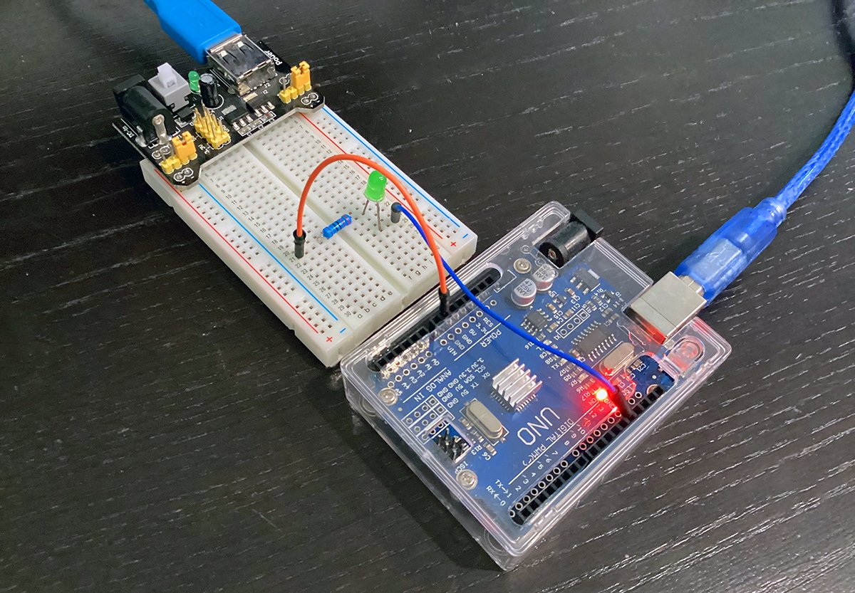
Remember there is a grid of metal rails under all the holes on the breadboard. No matter which way components are oriented on the breadboard, they must always form connections between components, the Arduino, and with jumper wires to complete the circuit.
If you already uploaded the Blink example to your Arduino, you should see the LED start to blink. Both the LED on the Ardunio and the one on the breadboard should blink in unison. If not, go back and check all your connections again.
Note that some electronic components such as LEDs are polar: current can only flow through them correctly in one direction. Other components such as most resistors are non-polar: current can flow the same through them in either direction.
You can play around with the timing value passed to the delay() function to speed up or slow down the blink rate of the LEDs. Try huge and tiny values and watch what happens.
By adding more digitalWrite() and delay() statements to your Sketch you can alter the blink pattern: for example, you can make the LEDs blink Morse Code.
Final example: a traffic light simulator
Now that you've seen how to blink your Arduino's LED, we'll use one final, slightly more complex example: we'll use a third-party UNO breakout board and an external traffic light sensor board to simulate a three-color traffic stop light.
In fact, there are many such stop-light sensors available, including simple ones on eBay for under $5. There is even a four-way one available from Jake on PCBWay's Projects pages.
Alternately, you can find a temporized one with a countdown timer LCD also on PCBWay.
In our example, we'll use the simplest three-light sensor and make it change colors at brief intervals, just like a real traffic light.
These traffic light boards usually have three or four pins: one for each colored LED, and one GND. The code is smilier to Blink, except that you turn all the lights off except one, wait using delay(), then turn that one off, and the next one on, in sequence.
First, we'll connect our traffic light sensor to a generic breakout shield we have installed on our Arduino UNO: breakout shields are shields containing banks of analog and digital pins, GND pins, Bluetooth, and serial cable connectors.
Our traffic light sensor has four pins: R, G, Y, and GND. We'll connect digital pins 9, 10, and 11 to R, G, and Y respectively, and the fourth pin, GND to a GND pin on our shield.
Now open the Arduino IDE and start a new Sketch. First, we'll define some things we'll need at the top of the Sketch above setup().
First, we define how many milliseconds are in a second so we can specify how many seconds to pass to delay();
#define kMillisecondsInSec 1000
Next, we define how many seconds we want the yellow light to be on for:
#define kSecondsForYellow ( kMillisecondsInSec * 4 )
Then we define which three pins we want to use for red, yellow, and green on the Arduino. Instead of using defines, we assign the pin values each to a global variable, in this case variables of type int (which is defined by C):
int RED = 9; int YELLOW = 10; int GREEN = 11;
Think of a variable as a named container whose contents (value) you can change whenever you want. Variables also have a type in order to specify what kind of values they can hold. Global variables can be accessed from anywhere in a program.
Variables declared inside of functions are called local variables and can only be used inside one function. This is called variable scope.
Next, we define global variables and assign calculations to them to simplify how we calculate seconds and milliseconds, and delay values for the green, red, and yellow lights in seconds. In this case we use a variable type called 'unsigned long int', which are like ints, but can hold larger values:
unsigned long int millisecondsInMinute = ( kMillisecondsInSec * 12 ); // # of milliseconds in 1 min. unsigned long int minutesForGreenAndRed = ( 1 * millisecondsInMinute ); // number of minutes to leave green, red lights on. unsigned long int yellowDelay = kSecondsForYellow; // Time to leave yellow light on. Yellow delay is shorter than red/green.
Now in setup() we define the pin modes for pins we defined above, one each for red, yellow, and green:
void setup( void ) { pinMode( RED, OUTPUT ); pinMode( YELLOW, OUTPUT ); pinMode( GREEN, OUTPUT ); }
This tells the Arduino we will use those three pins for output values (in this case on or off).
In loop(), we start by turning the red/yellow lights off, the green light on, then we wait for onDelay seconds:
void loop( void ) { // Green - Start digitalWrite( RED, LOW ); digitalWrite( YELLOW, LOW ); digitalWrite( GREEN, HIGH ); delay( onDelay );
After onDelay, we turn the green light off, the yellow light on, then wait for yellowDelay seconds:
digitalWrite( GREEN, LOW ); digitalWrite( YELLOW, HIGH ); delay( yellowDelay );
After yellowDelay, we turn the yellow light off, the red light on, and wait for onDelay seconds:
// Red digitalWrite( YELLOW, LOW ); digitalWrite( RED, HIGH ); delay( onDelay );
Finally, after onDelay elapses, we turn the red light off, effectively resetting the simulation:
digitalWrite( RED, LOW ); }
The next time the loop runs, the same sequence repeats, starting with the green light. This loop will run forever until stopped. We now have a working traffic light simulator:
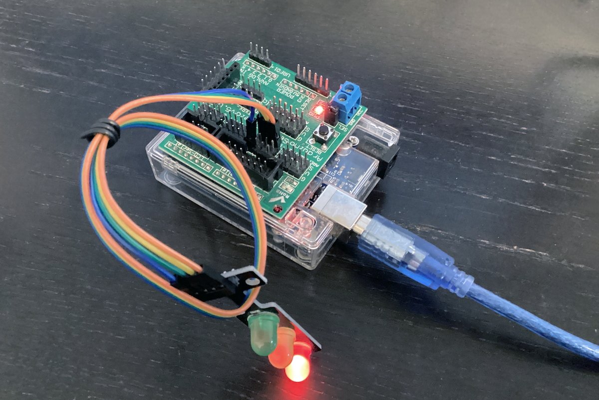
Once you've uploaded the Sketch to your Arduino, if you plug in an external power supply to your Arduino's DC barrel jack, and unplug its USB cable, the simulation will continue to run.
This is one of the benefits of Arduino: once you program the microcontroller, it can run a program independently of a host computer.
You can make Arduinos do just about anything - act as sensors, display info, wait for input, make sounds, use cameras and send images back to other devices, monitor conditions, drive motors, and so on.
There are a few introductory books worth reading for learning Arduino's C-like language:
- Programming Arduino: Getting Started with Sketches
- Arduino Essentials
- Beginning C for Arduino
- Learning C for Arduino
- Arduino Technical Reference
- Arduino Cookbook
- Mastering Arduino
These simple examples should get you started programming Arduino. As you build your programming skills and gain confidence, you can expand to bigger examples.
In future articles, we'll explore programming Arduino devices, shields, and busses such as I2C and SPI, and creating complex device environments.